
Daf ZF Intarder With Idling Loss Reducing Device CF 75 CF 85 XF 95 YTZ 95 XF105 Official Component Manual
27.23 €
195 in stock

Daf ZF Intarder With Idling Loss Reducing Device CF 75 CF 85 XF 95 YTZ 95 XF105 Official Component Manual
The Best PDF Manuals Online Includes : Bookmarks + Searchable Text + Index = Fast Navigation And Best Organization !
This is the COMPLETE Official Component manual for the Daf Trucks.
This manual contain high-quality diagrams, schematics, pictures, step-by-step instructions on how to service and repair your trucks DAF
This PDF file is Bookmarked and SEARCHABLE to make what you need easy to find.
Models And Serials :
All Years & Serials Covered
CONTENTS :
Preface…………………………………………………………….3
Work safety ……………………………………………………4
Instruction for repairs ………………………………….5
Required materials ……………………………………….7
Adjustment data……………………………………………8
Tightening torques …………………………………….. 9
Special tools ………………………………………………….14
Heat exchanger position: horizontal………….19
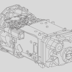
Transmission illustration ………………………………20
Sectional drawing ………………………………………….21
1.Disassembly
1.1Remove oil filter…………………………………………………1-1
1.2Remove heat exchanger, solenoid valve, reservoir and temperature sensor …….1-2
1.3Reservoir disassembly ………………………………………1-3
1.4Removal of Intarder from basic transmission …….. 1-4
1.5Oil pump removal ……………………………………………………. 1-5
1.6Removal of control unit housing and valves ………..1-7
1.7Spur gear removal………………………………………………………1-8
1.8Removal of stator………………………………………………………..1-9
1.9Removal of rotor………………………………………………………….1-10
1.10Idling reduction valve………………………………………………. 1-11
1.11Disassembly of preload valve…………………………………..1-11
2.Assembly
2.1Installing the idling reduction valve ………….2-1
2.2Installing the preload valve ………………………..2-1
2.3Rotor installation …………………………………………..2-2
2.4Stator assembly…………………………………………………………………………………………………..2-3
2.5Stator, taper roller bearing and spur gear installation ……………………………….2-4
2.6Fitting taper roller bearing to rotor and adjusting taper roller bearing .. 2-5
2.7Fitting valves and attaching the control housing………………………………………2-6
2.8Oil pump assembly and mounting……………………………………………………………….2-8
2.9Measuring end float………………………………………………………………………………………..2-9
2.10Reservoir assembly………………………………………………………………………………………. 2-12
2.11Heat exchanger, solenoid valve, reservoir and temperature sensor assembly……………… 2-13
2.12 Fitting heat exchanger …………………………………………………………………………………………………………… 2-14
========================================

Discover more from The Best Manuals Online
Subscribe to get the latest posts sent to your email.